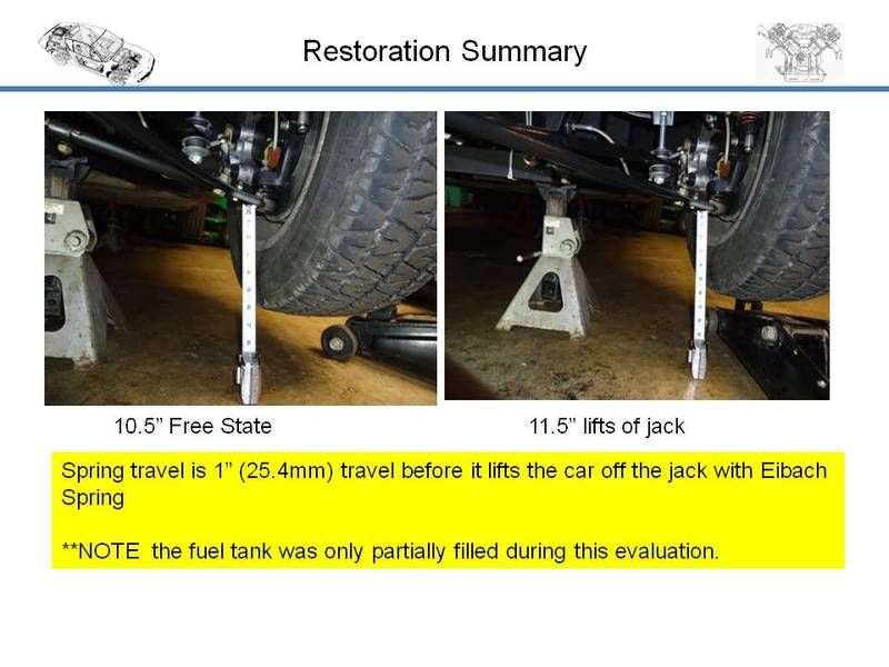
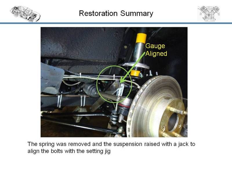
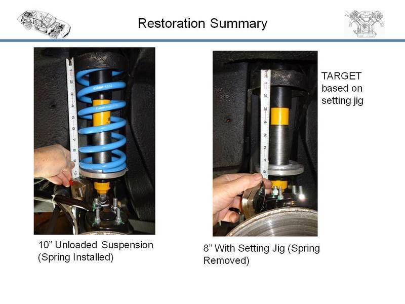
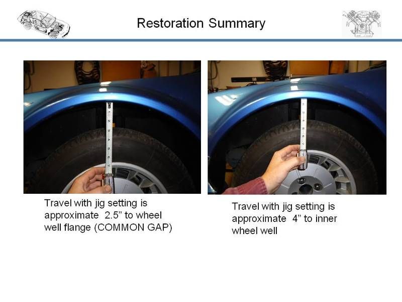
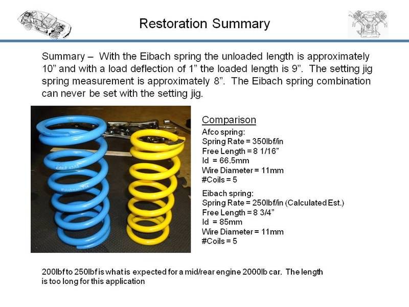
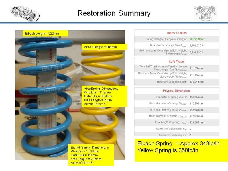
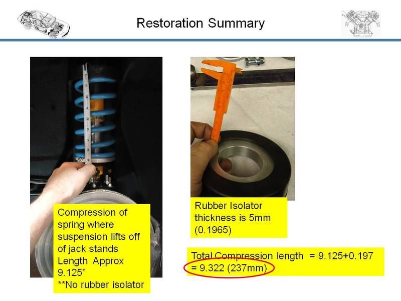
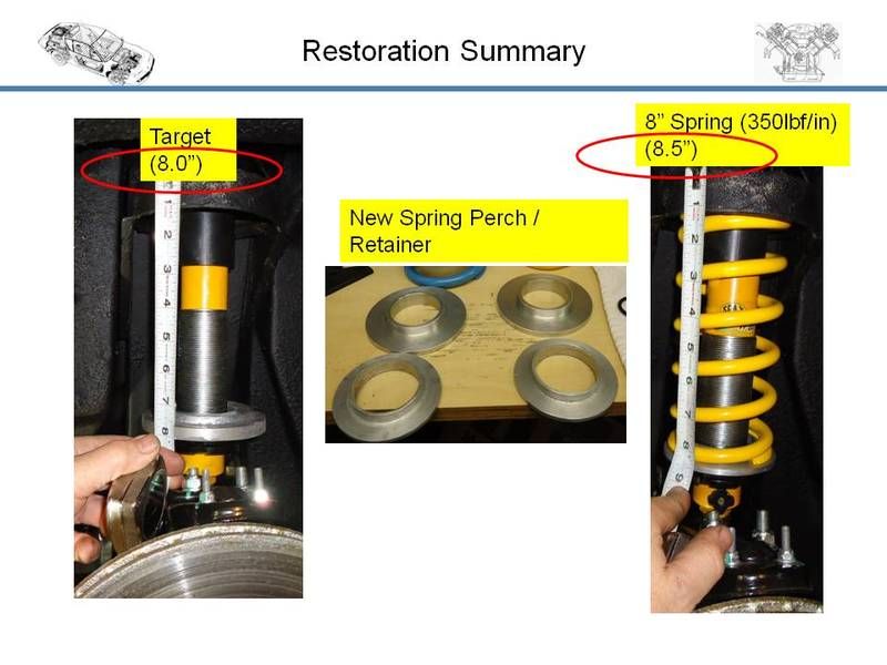
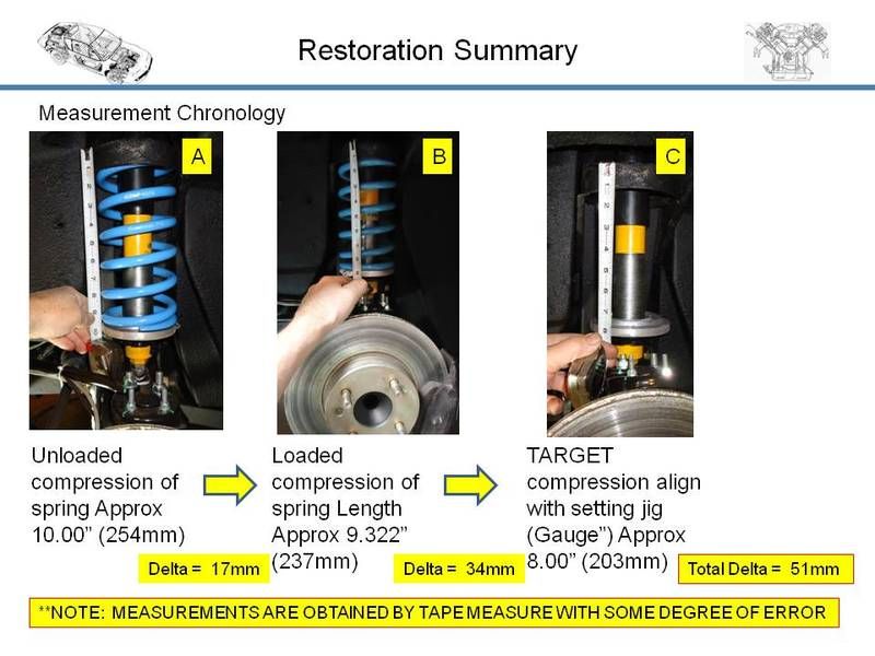
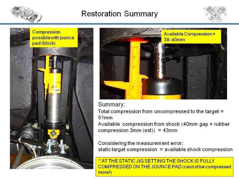
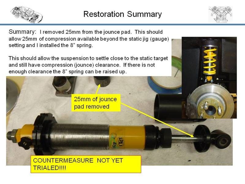
dallarax19 wrote:OK, I think I made some headway. The FAR guys brought up a standard "jig" that sets the relationship of the shock bolt head to the lower control arm pivot bolt head. The key dimension was reported as 280mm. So I just did some quick measurements and a basic kinematic swing study and the indication is my suspension is not compressed enough.
Shame about the radiator leak, is the plug made from plastic? Don’t give up, you’ll get there in the end. Do a bit of work on the Fiat for a change.
Some more information. GTA and A610 owners may switch off now.
 ONLY
ONLY 
A qualification regarding front parallelism. In the ‘Service information’ at the end of the MDR is data for the Phase 2 which is probably where you found the settings shown in your first post on this thread. It does say 2 mm toe-out total for the front in static position. My understanding of static position is when the static tools are in position at the front and rear suspension. These tools are simple gauges that set the suspension in a certain position, the static position; see the attached page from the MDR.
One thing I’ve not been able to determine from the MDR is whether the car should be in the loaded condition when the gauges fit. The MDR, when referring to ride height on page J14a, states that the check is made when the vehicle is on a level surface, the fuel tank is full, tyre pressures are correct and two people are on board. Where the static tools are mentioned I can’t find any reference to the loaded condition of the car. In reality I can’t imagine static position checks being made only when two people were available and the car had a full tank of petrol.
As well as the MDR the previous owner of the car gave me a copy of a French Revue Technique for the A310 4 cylinder and V6, but only for the Phase 1. This has a drawing of the front and rear static tools, which is attached. This drawing shows some similarity to the 280 mm dimension that FAR gave you. The drawing note states that both gauges apply to the 4 cylinder and that the top gauge (AV) is also suitable for the front of the V6. It’s not too clear on the drawing but the centre distance of the two holes in the gauge is 298 mm but bear in mind that this is for the Phase 1, the 280 mm dimension you were given may be correct for the Phase 2.
Just one observation about your photo. I could be wrong but it looks as if there’s a jack under the chassis (painted grey) and something supporting the outboard end of the lower suspension arm. Even if the weight of the car is being taken by the support under the suspension arm I’d be inclined to only make the measurement when the car wheels are supporting the weight as the load point will move out and the wheel lever arm be greater. As you’ll be aware, as load is taken off the wheel the distance you’re measuring between the bolt heads reduces. I was just wondering whether the load was being taken by the wheel and not the suspension.
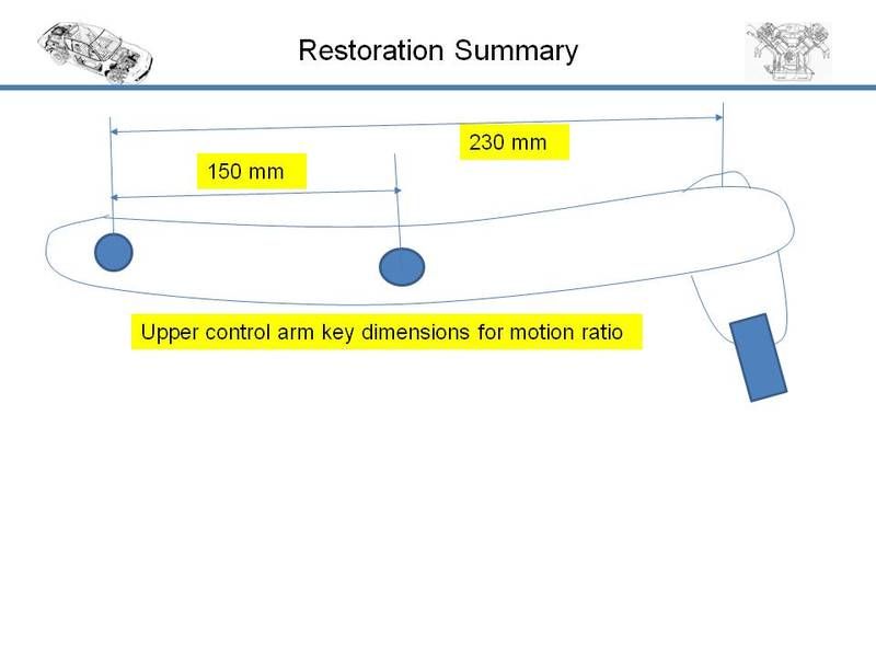
I’ll come back again with some dimensions I’ve taken from the top suspension arm.


